The LILYGO® TTGO T5 V2.3.1_2.13 board is at the center of this device design as it has a 2.13in ePaper SPI display built into it along side buttons & USB/microSD ports.
It's an ESP32 based board with all standard supporting circuitry & memory. It also has built in battery control circuits and a convenient 1.25mm pitch JST connector.
An 8 way PCB socket connector must be connected using 6 wires soldered to specific pins on it and the PCB socket connector. Continue reading for instructions on how to do this.
Parts
| Part | Description |
|---|---|
| LILYGO® TTGO T5 V2.3.1_2.13 | 2.13in EPD and ESP32 board with battery charging. Only DEPG0213BN version is supported so far. |
| 2.54mm pin socket | 8 Way, 1 row, socket |
| Wire | Six colors of wire. |
Build Steps
Step 1 - Attach 6 lengths of wire.
Get the following parts ready before starting this step.
| Part | Description |
|---|---|
| LILYGO® TTGO T5 V2.3.1_2.13 | 2.13in EPD and ESP32 board with battery charging. Only DEPG0213BN version is supported so far. |
| Wire | Six colors of wire. |
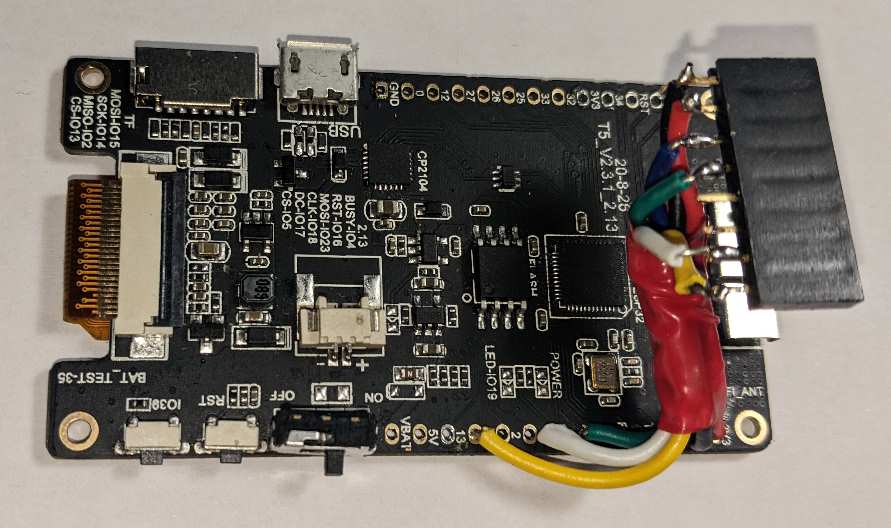
The lengths of wire should be attached to the following pins.
| Color | Purpose | LilyGO Pin |
|---|---|---|
| Black | Ground | GND |
| Red | 3.3v | 3.3 |
| Blue | I2C SDA | 21 |
| Green | I2C SCL | 22 |
| White | Enable Sensor | 19 |
| Yellow | Reading Ready | 15 |
Enough wire must be left to complete the remaining steps. See image below:-
Step 2 - Route & bundle wires
Get the following parts ready before starting this step.
| Part | Description |
|---|---|
| LILYGO® TTGO T5 V2.3.1_2.13 | 2.13in EPD and ESP32 board with battery charging. Only DEPG0213BN version is supported so far. |
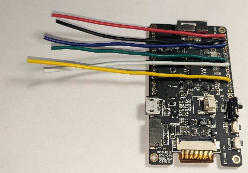
Route the wires towards the end of the LILYGO® TTGO T5 board opposite the buttons and USB ports. Create bends and use tape to secure the wires as a neat bundle.
See image below for desired result:-
Step 2 - Solder 8 way socket
Get the following parts ready before starting this step.
| Part | Description |
|---|---|
| LILYGO® TTGO T5 V2.3.1_2.13 | 2.13in EPD and ESP32 board with battery charging. Only DEPG0213BN version is supported so far. |
| 2.54mm pin socket | 8 Way, 1 row, socket |
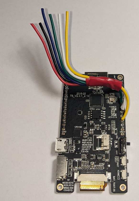
Connect each of the wires to the appropriate pin on the 8 way socket.
This socket will attach to the 8 way header on the base of the sensor assembly. Thefore the pin connections must be as follows:-
| Color | Purpose | Socket PIN |
|---|---|---|
| Black | Ground | 1 |
| Red | 3.3v | 2 |
| Blue | I2C SDA | 3 |
| Green | I2C SCL | 4 |
| White | Enable Sensor | 7 |
| Yellow | Reading Ready | 8 |
The objective is to achieve enough slack to make assembly possible but also to avoid using excessive lengths of wire and damaging connections during assembly.
See image below for desired result:-