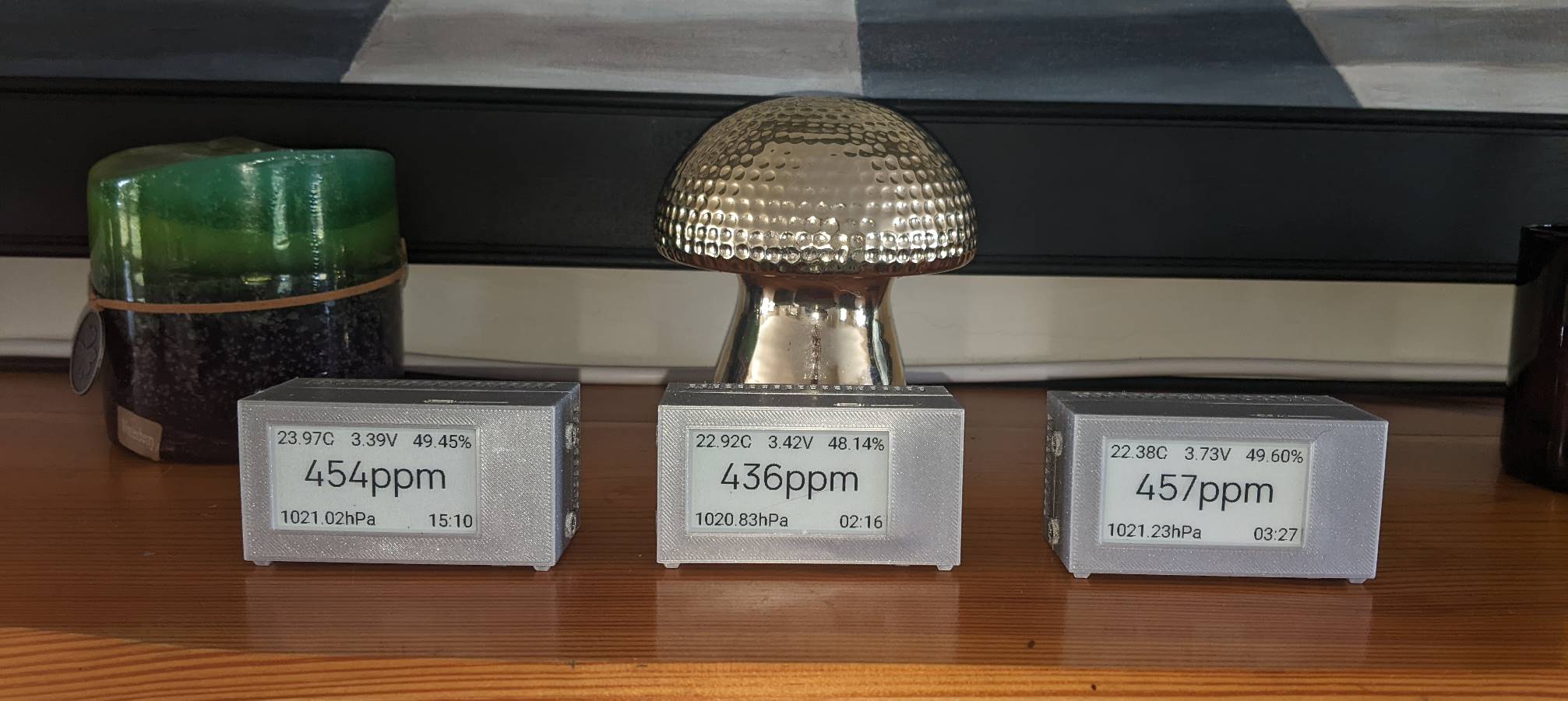
A highly portable AirMeter.io device with an ePaper display that has great battery life even when connected to WIFI. The display provides live readings, charts and access to the CO2 sensor calibration sequence.
The AirMeter.io platform gives this device a full suite of web and management features.
The device is produced in several stages/parts which are described below.
Sensor Assembly
The Sensor Assembly is a small PCB (7cm x 3cm) on which the sensors are mounted. On the underside which is exposed when it is screwed in place is a set of 8 way right angle PCB pins.
These pins connect to the 8 way PCB socket wired to the LILYGO® TTGO T5 board.
See the Senseair Sunrise Assembly build instructions to build a board for the Sunrise CO2 sensor.
Prepare LILYGO® TTGO T5 board
The LILYGO® TTGO T5 V2.3.1_2.13 board provides the following:
- ESP32, antenna (WIFI, BT and ESP NOW) and flash memory.
- A 2.13in ePaper SPI display.
- Battery control circuitry.
- USB serial adapter & SD Card reader.
- Action and reset buttons.
An 8 way PCB socket connector must be connected using 6 wires soldered to it to and the connector.
See Prepare LILYGO® TTGO T5 board for instructions.
Attach 1.25mm JST connector to battery
The LILYGO® TTGO T5 board board uses a 1.25mm pitch JST connector to attach to the battery. The FT103450P battery must have such a connector attached.
See Prepare Battery for instructions.
3D print & assemble
The various casing parts must be printed using a suitable 3D printer. Once printed the parts must be assembled following a specific sequence.
See 3D print & assemble for where to get the 3D models and instructions on how to assemble the full device from its parts.