

Required Components
Before assembly can begin ensure you have the following components prepared and ready.
- A completely assembled Sensor Assembly.
- A LILYGO® TTGO T5 board with the connector attached.
- A FT103450P with a 1.25mm JST connector attached.
- The 3D printed parts from the next section.
- 10x M2x6mm self tapping screws.
3D Printed Parts
The casing for the CO2 monitor is printed using a 3D printer. The models are available at https://github.com/airmeter-io/epd213. The table below describes each part and its purpose.
| Part | Name | Dimensions (mm) | Description |
|---|---|---|---|
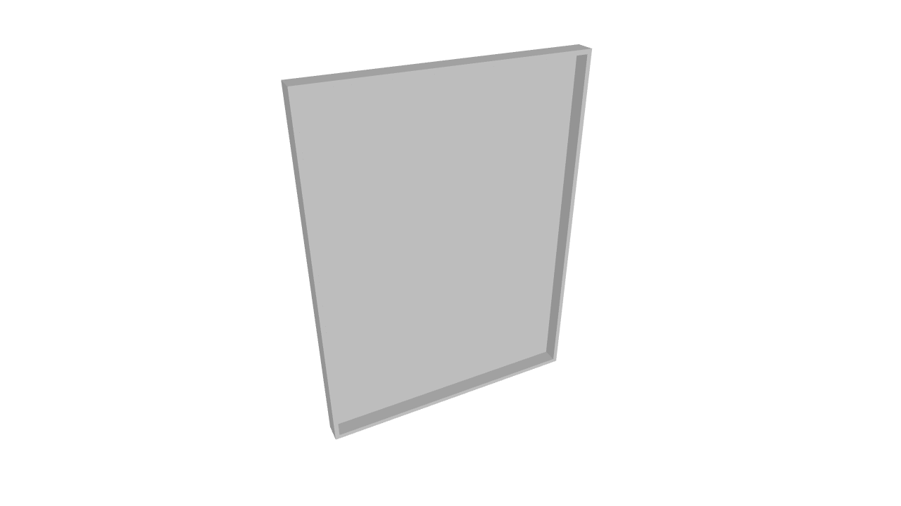
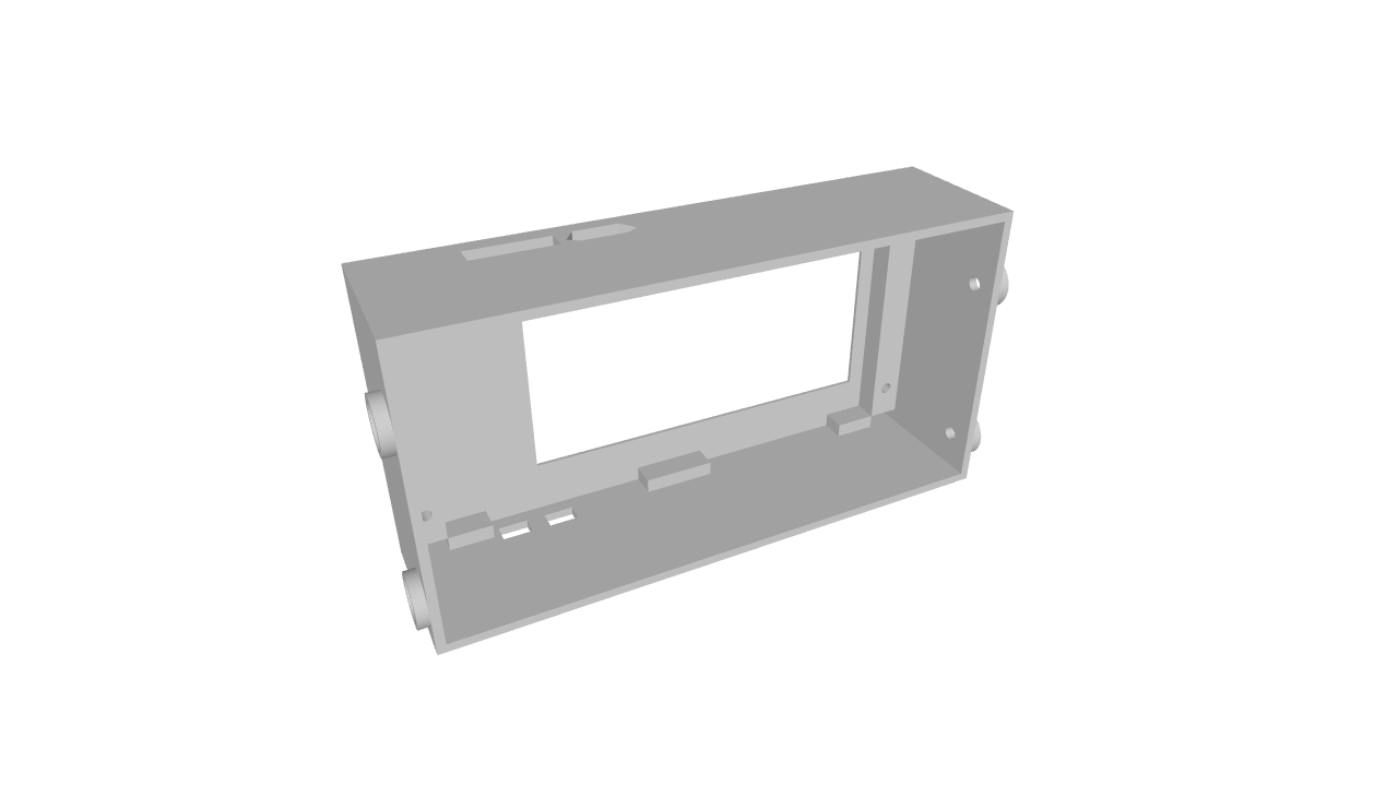 |
Front | 78.4x41.4x20.5 | The front panel of the device into which the LILYGO® TTGO T5 board is held into place by the "battery holder" part |
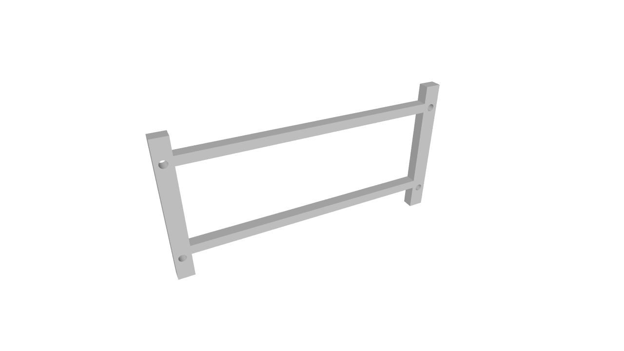 |
Battery Holder | 75.5x38.5x3 | Holds the LILYGO® TTGO T5 board in place and provides a safe resting point for the battery. |
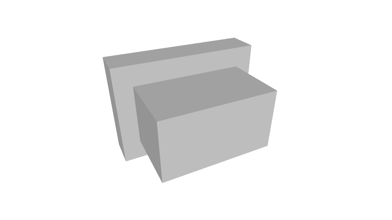 |
Action Button | 5x3.5x3.5 | A button which extrudes past the casing for controlling the device |
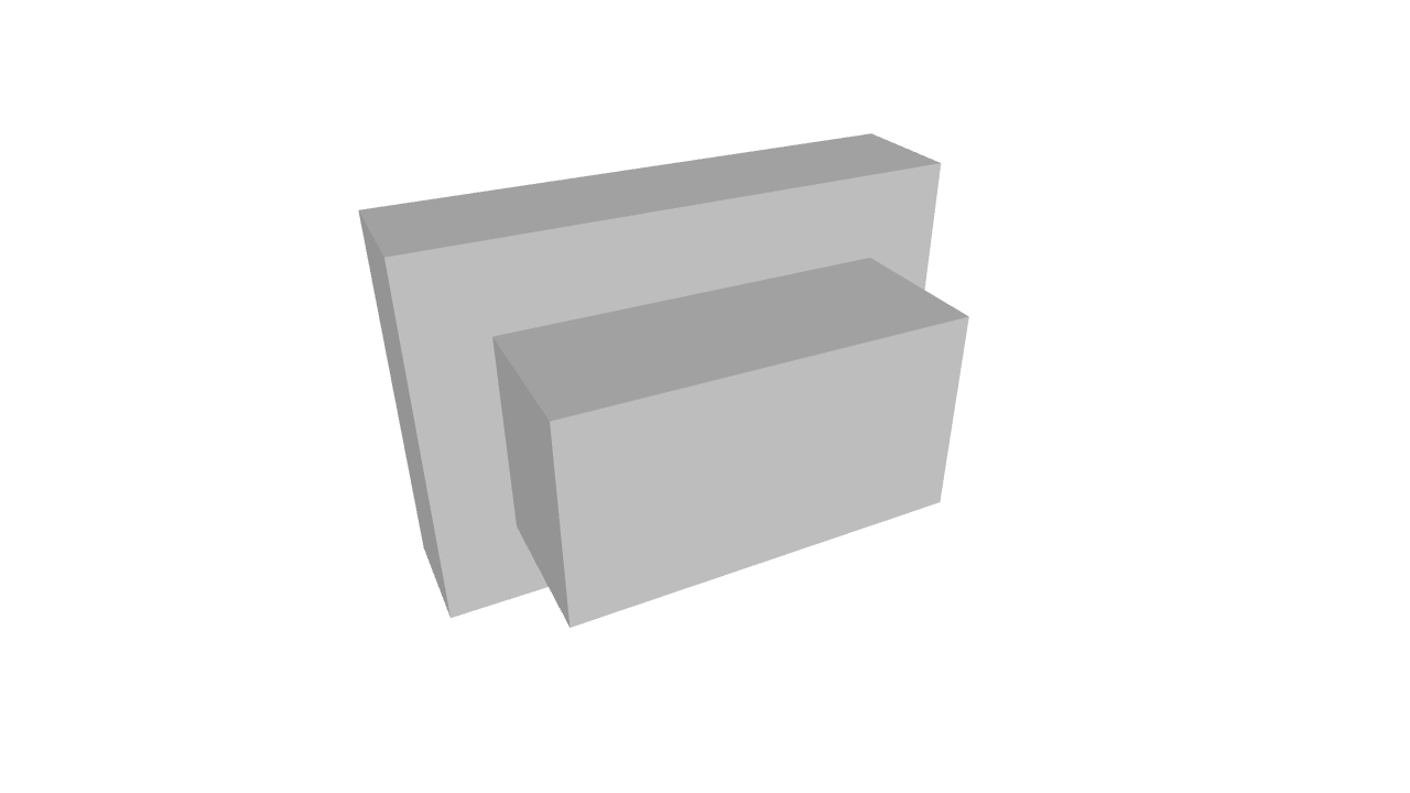 |
Reset Button | 5x3.5x2.5 | A button which does not extrude past the casing which is used for the reset function. |
 |
Battery Protector | 36.2x48.2x2.6 | Fits on top of the FT103450P battery |
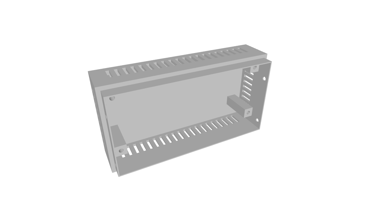 |
Back | 78.4x41.4x21.5 | The Sensor Assembly screws into this part onto pillars. The sensors themselves face upwards into the area in which there are grills to allow airflow. The pillars have been sized to ensure a minimum clearance around a Senseair Sunrise. |
Step 1 - Assembling the Front & Back
The Front
The Action & Reset buttons must be carefully put into their holes within the Front panel. Gravity must be relied upon whilst inserting the LILYGO® TTGO T5 board first into the USB/microSD holes and then carefully down holding the two buttons in place.
Then the Battery Holder must whilst keeping the previously inserted parts together be slid in on top. One side has a wider space this should be used to accomodate the USB/microSD ports.
The battery holder must then be screwed into place using 4 screws. Before and after doing this ensure that the buttons are correctly aligned and functional.
The Back
The back panel is simply a casing to hold the Sensor Assembly. Therefore screw the Sensor Assembly onto the pillars that are provided.
It will only be possible to screw into two pillars. This is sufficiant.
Note that the 8 way right angle pin connector should be orientated so that it is closest to the case. You will notice one set of pillars are right beside the edge.
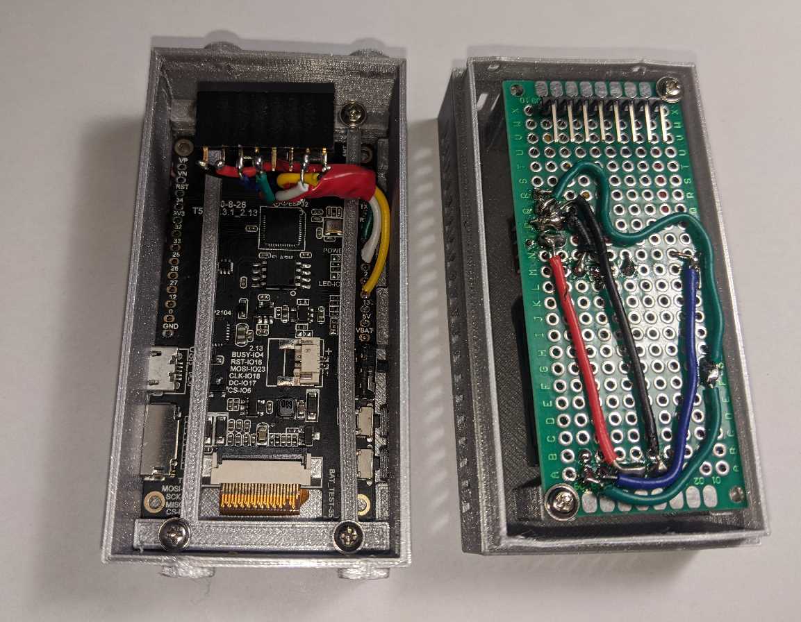
Step 2 - Putting it all together
First connect the Battery to the JST connector on the LILYGO board which has been put into the Front part. Now neatly as possible route the wires to avoid them being crushed.
Stretch the 8 way socket connector attached to the LILYGO® TTGO T5 board so that you can slide the 8 way right angle pins on the Sensor Assembly onto this connector.
Now use the a small flathead screw driver to pull the LILYGO board powerswitch to the off position and then back to the on position.
Slide the Battery Protector piece ontop of the battery and make sure that it settles inside the raised edges of the protector.
Carefully push the Front and Back together holding tightly. Whilst continuing to hold use 4 screws in the provided screw holes to hold the case together.