Overview
The Sensor Assembly is a small PCB (7cm x 3cm) on which the sensors are mounted. On the underside which is exposed when it is screwed in place is a set of 8 way right angle PCB pins.
These pins connect to the 8 way PCB socket wired to the LILYGO® TTGO T5 board.
Once completed this part will appear in as shown in the image below.
Parts
| Part | Description |
|---|---|
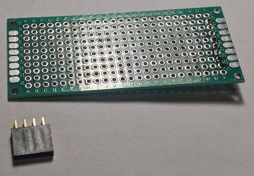
| 22402A-17 | 3cm x 7cm double sided universal PCB |
| 006-0-0007 | Senseair Sunrise CO2 sensor |
| BME280-5V | BME280 breakout board the 4 pin version which is usually labeled as supporting 5v due to the regulator used |
| 2.54mm socket | 4 Way 1 Row Straight PCB Socket |
| Through Hole | |
| 2.54mm pin header | 4 Way, 1 row, straight pin header |
| 2.54mm pin header | 5 Way, 1 row, straight pin header |
| 2.54mm pin header | 8 Way, 1 row, right angle pin header |
| Wire | Six colors of wire. |
Wire Colors
| Color | Purpose |
|---|---|
| Black | Ground |
| Red | 3.3v |
| Blue | I2C SDA |
| Green | I2C SCL |
| White | Enable Sensor |
| Yellow | Reading Ready |
Build Steps
- Step 1 - Attach the 8 way right angle pin header
- Step 2 - Attach 4 way PCB Socket for BME280 board
- Step 3 - Mounting CO2 Sensor pin headers
- Step 4 - Attach Sunrise CO2 Sensor
- Step 4 - Attach Sunrise CO2 Sensor
- Step 5 - Wire 3.3V VIN (Red wire)
- Step 6 - Wire GND (Black wire)
- Step 7 - Wire I2C (Green and Blue wire)
- Step 8 - Wire CO2 sensor control (White and yellow wire)
Step 1 - Attach the 8 way right angle pin header
Get the following parts ready before starting this step.
| Part | Description |
|---|---|
| 22402A-17 | 3cm x 7cm double sided universal PCB |
| 2.54mm pin header | 8 Way, 1 row, right angle pin header |
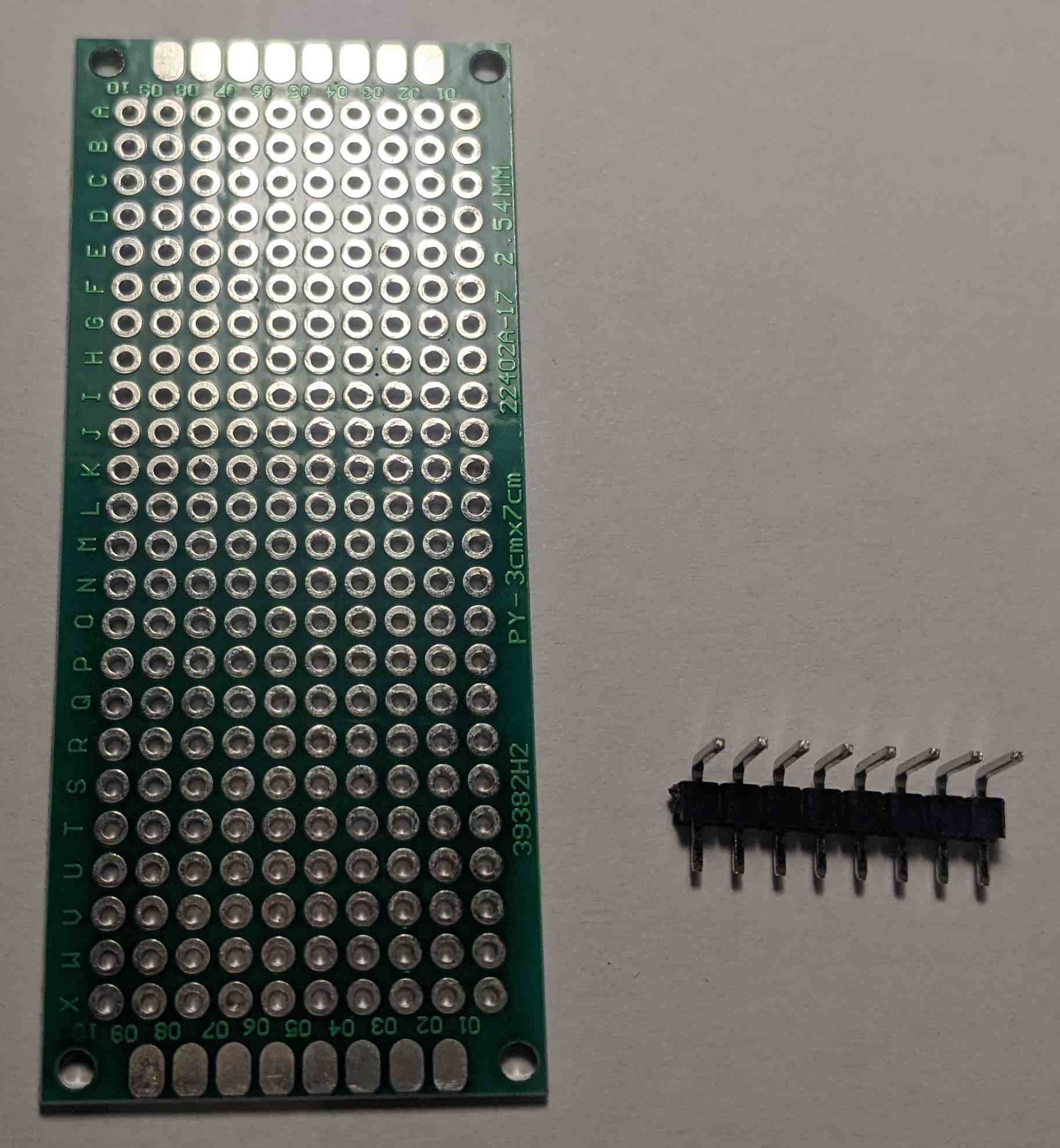
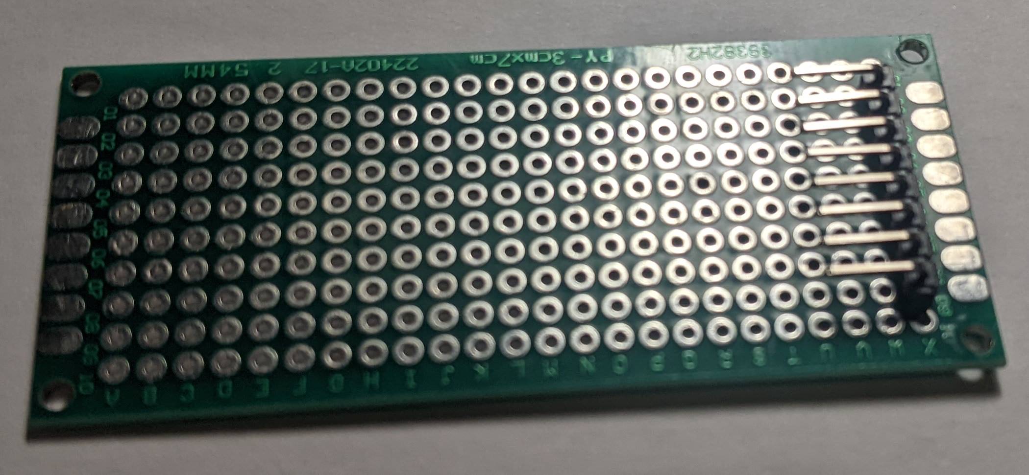
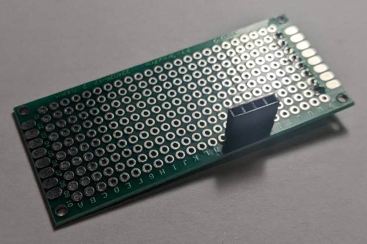
At one thin (10 holes/3cm wide) end of the PCB attach the pin header to the PCB using solder. The pins must face inwards towards the other thin end of the PCB.
After completing this step the PCB should appear as in the the image below.
Step 2 - Attach 4 way PCB Socket for BME280 board
Get the following parts ready before starting this step.
| Part | Description |
|---|---|
| 22402A-17 | 3cm x 7cm double sided universal PCB |
| 2.54mm socket | 4 Way 1 Row Straight PCB Socket Through Hole |
- Orientate the PCB so that the PIN header is underneith and on the right hand side.
- At the bottom and six holes in from the right of the PCB mount the 4 way socket using solder.
The PCB will appear as shown in the image below when this step is completed.
Step 3 - Mounting CO2 Sensor pin headers
Get the following parts ready before starting this step.
| Part | Description |
|---|---|
| 22402A-17 | 3cm x 7cm double sided universal PCB |
| 2.54mm pin header | 4 Way, 1 row, straight pin header |
| 2.54mm pin header | 5 Way, 1 row, straight pin header |
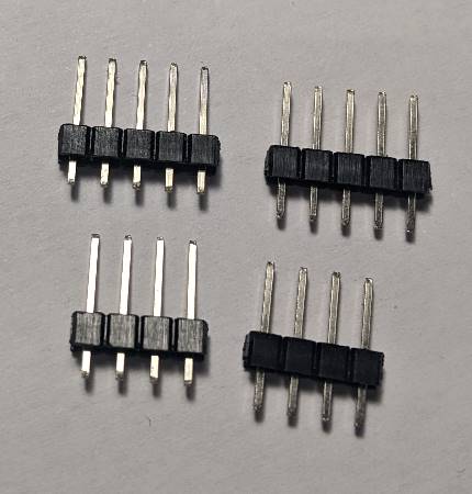
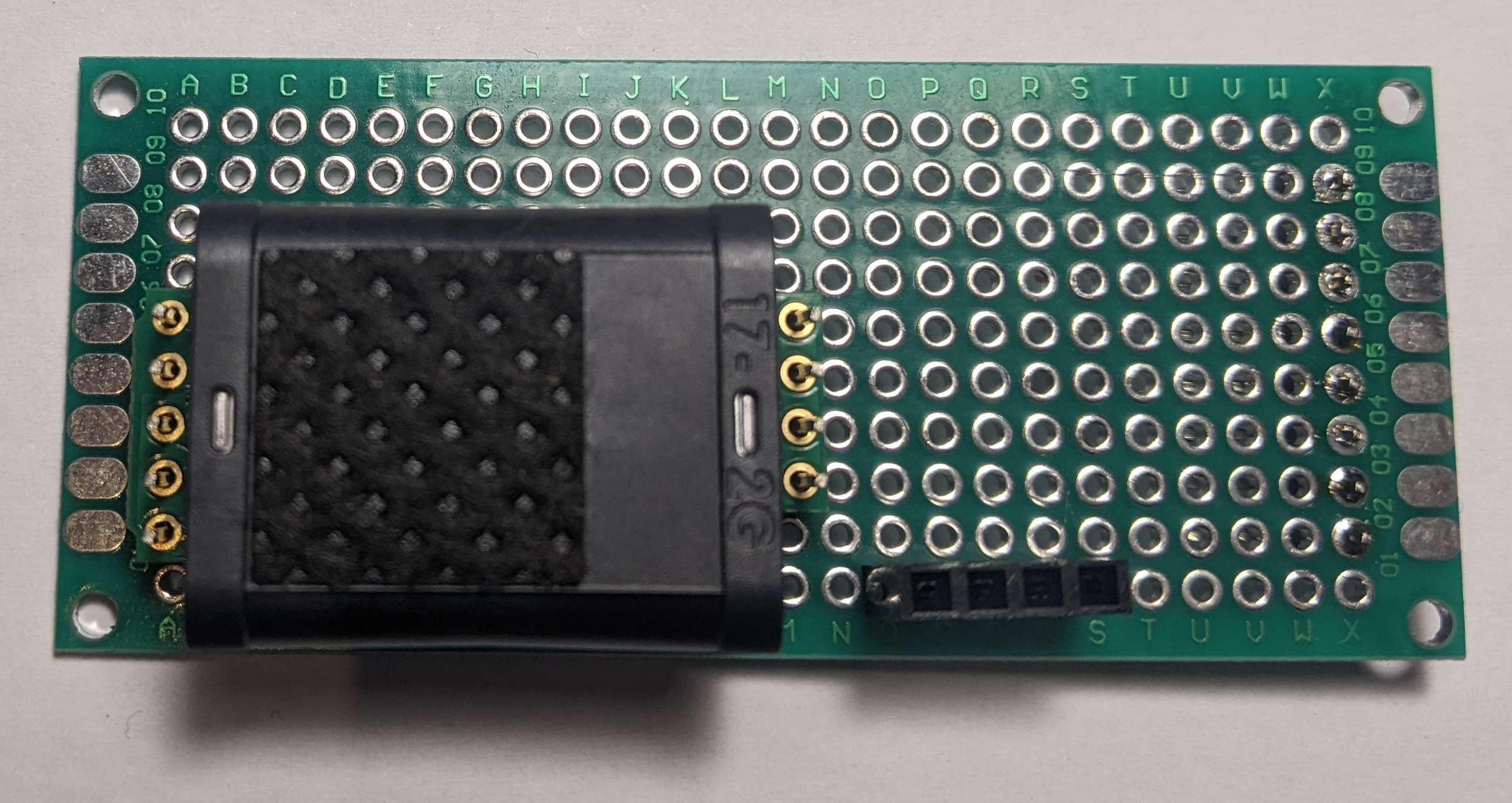
The pin headers need to be adjusted so that the minimum length extrudes from the rear of the PCB. The pins will stick out on the PCB side to which the sensor is attached.
This is important to allow the PCB to fit within the case.
The following image shows adjusted pin headers on the left and the original position of the plastic spacer on the right.
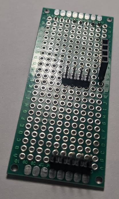
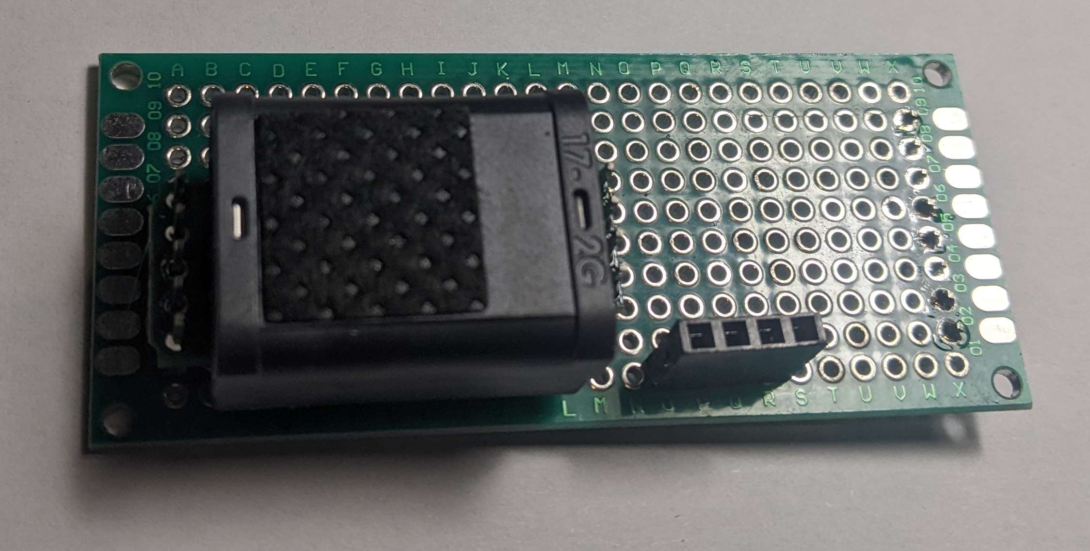
- Orientate the PCB so that the 8 way right angle PIN header is underneith and on the right hand thin side.
The PCB socket attached in the previous step will be on the side facing upwards. - Solder the 5 way pin header on the left hand (thin) side with one hole separating it from the bottom of the PCB.
- Solder the 4 way pin header 13 holes from the left hand (thin) side with two holes separating it from the bottom of the PCB.
The PCB will appear as shown in the image below when this step is completed.
Step 4 - Attach Sunrise CO2 Sensor
Get the following parts ready before starting this step.
| Part | Description |
|---|---|
| 22402A-17 | 3cm x 7cm double sided universal PCB |
| 006-0-0007 | Senseair Sunrise CO2 sensor |
Place the Senseair Sunrise CO2 sensor on the pins attached in the previous step. The pins must align exactly with the Senseair Sunrise PCB if they don't the previous step was not completed correctly.
Solder each of the pin headers to the Senseair Sunrise sensor PCB. The PCB will appear as shown in the image below when this step is completed.
Step 5 - Wire 3.3V VIN (Red wire)
Get the following parts ready before starting this step.
| Part | Description |
|---|---|
| 22402A-17 | 3cm x 7cm double sided universal PCB |
| Wire | Red wire |
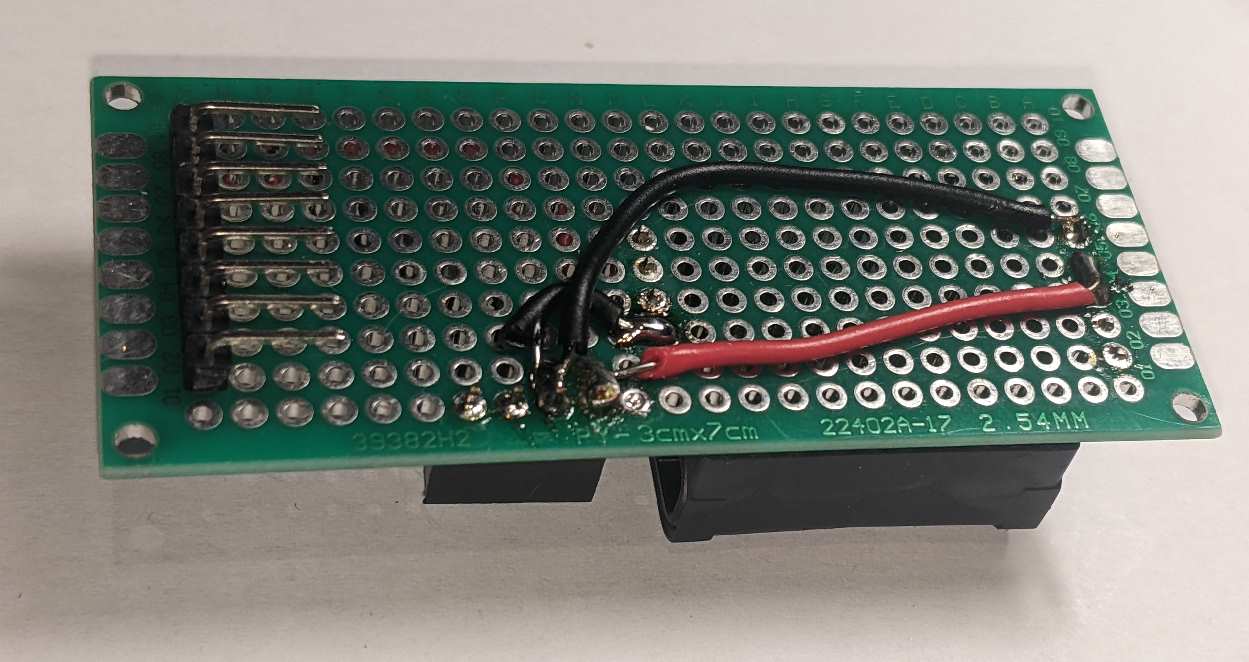
Place the PCB so that the CO2 sensor & BME280 socket are on the side facing upwards. Orienate it so that the BME280 socket is on the bottom side and the 8way header pins are on the left (actual pin connectors on the underside).
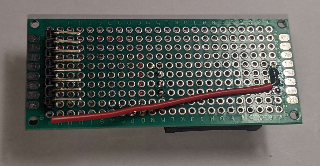
Solder a piece of red wire to pin 2 on the 8 way right angle connector whos pins are on the right hand side. See image below.
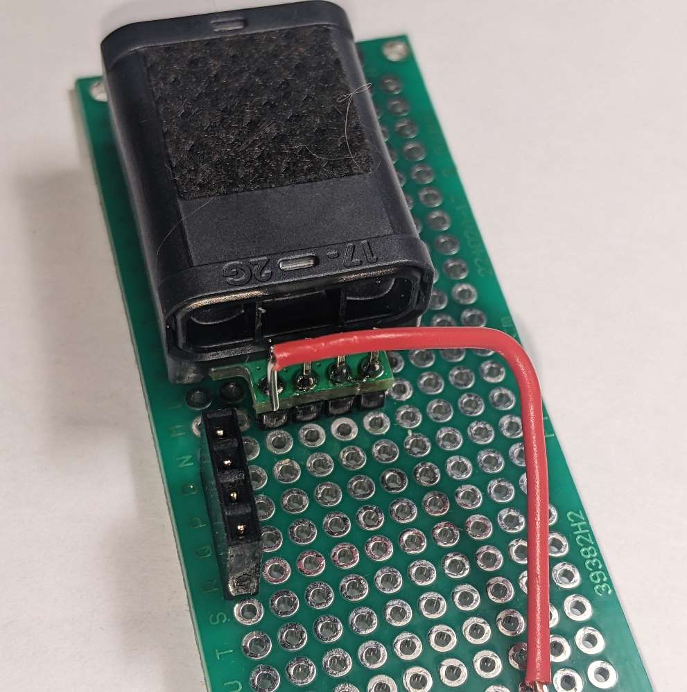
Cut the wire and orientate it in the manner shown in the image below. The end of the wire should be stripped to a length which allows it to pass through the hole above the left hole on the BME280 socket and touch the left BME280 socket pin on the otherside of the PCB.
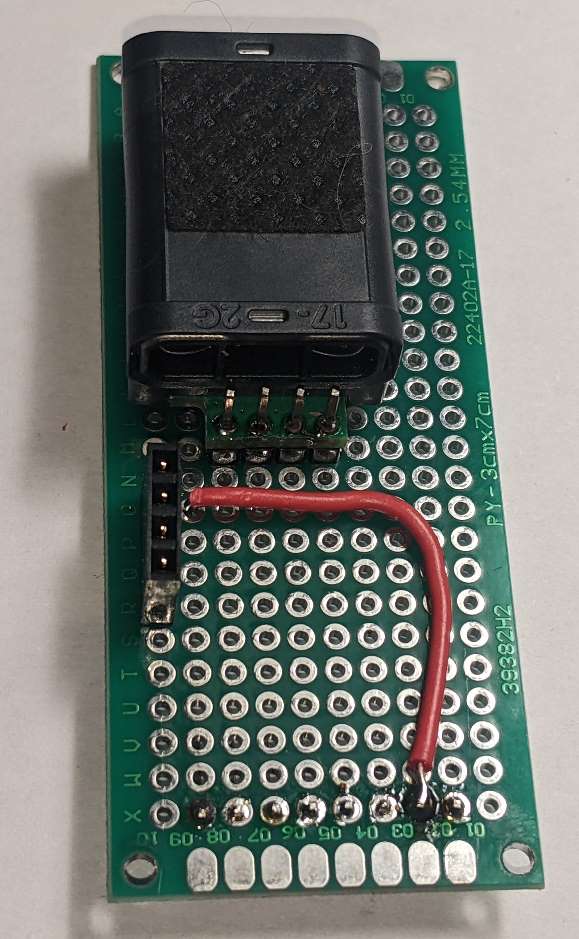
Turn the PCB over and ensure the BME280 socket pins are on the bottom side. The 8 way right angle connector will be on the left hand side.
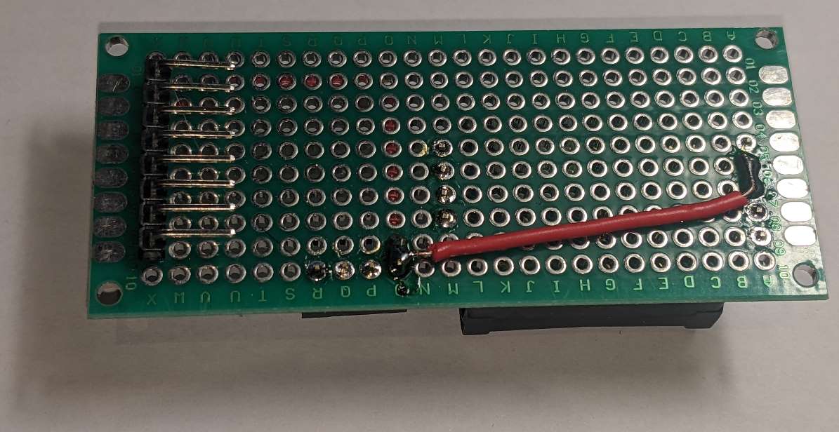
Attach a piece of red wire to the two pins three up from the bottom of the PCB on the far right hand side. See the image below.
Shorten and strip the wire so that it can connect with the wire coming from the other side of board and the right hand BME280 socket pin.
Solder the pin and the two wires together. The result should look similar to the image below.
Step 6 - Wire GND (Black wire)
Get the following parts ready before starting this step.
| Part | Description |
|---|---|
| 22402A-17 | 3cm x 7cm double sided universal PCB |
| Wire | Black wire |
Place the PCB so that the CO2 sensor & BME280 socket are on the side facing upwards. Orienate it so that the BME280 socket is on the bottom side and the 8way header pins are on the left (actual pin connectors on the underside).
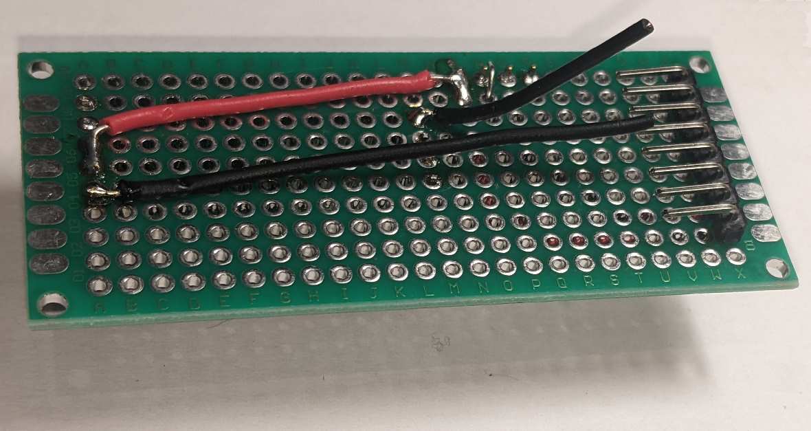
Solder a piece of black wire to pin 1 on the 8 way right angle connector who's pins are on the right hand side. This wire should be the right length to neatly go through the PCB next to the VIN connection.
Again leave enough stripped wire to touch the GND pin on the BME280 socket. See image below.
Turn the PCB so that the right angle pins are on top and the CO2 sensor is on the bottom.
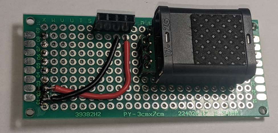
Solder two lengths of cable onto the GND and COMSEL pins of the Senseair Sunrise sensor. The GND pin will require a longer length than the COMSEL pin. See image below:-
Shorten and strip the two lengths of wire just soldered so that they neatly reach the GND pin of the BME280 socket and GND wire coming from other side of the PCB.
Solder the two pieces of wire, the BME280 GND pin and the GND wire from the other side of the PCB together. See image below:-
Step 7 - Wire I2C (Green and Blue wire)
Get the following parts ready before starting this step.
| Part | Description |
|---|---|
| 22402A-17 | 3cm x 7cm double sided universal PCB |
| Wire | Green & Blue wire |
The two colors of wire have the following meanings.
| Color | Purpose |
|---|---|
| Blue | I2C SDA |
| Green | I2C SCL |
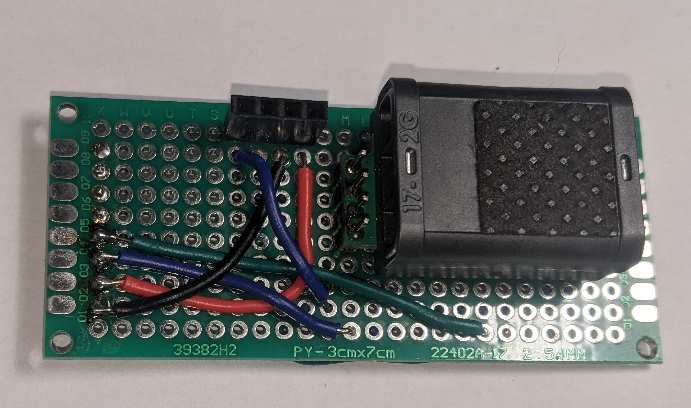
Place the PCB so that the CO2 sensor & BME280 socket are on the side facing upwards. Orienate it so that the BME280 socket is on the bottom side and the 8way header pins are on the left (actual pin connectors on the underside).
Solder a length of blue wire (I2C SDA) to pin 3 on the 8 way right angle connector. Then solder a length of green wire (I2C SCL) to pin 4 on the same connector.
Adjust the length on each wire so that they both go through to the other side of the PCB at a location where there is space to connect wires on the other side.
Finally place a length of blue wire (I2C SDA) to connect from the blue "junction point" back to the BME280 socket SDA pin. This will be soldered from the other side of the board.
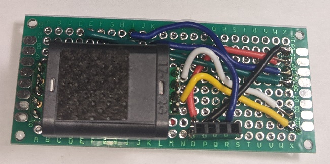
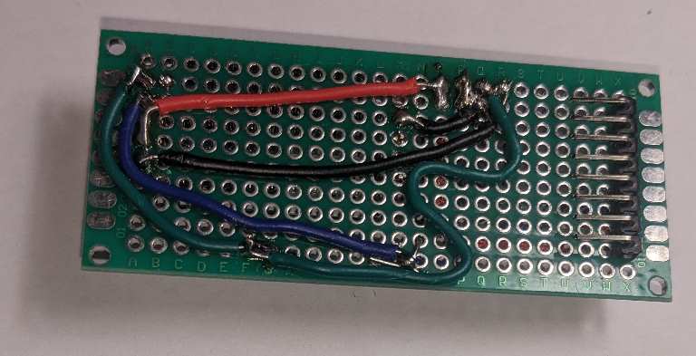
Turn the PCB so that the right angle pins are on top and the CO2 sensor is on the bottom.
Solder the blue (I2C SDA) wire connections together and add an additional piece of blue wire to connect the Senseair Sunrise I2C pin.
Solder the blue (I2C SDA) wire to the BME280 socket SDA pin.
Solder the green (I2C SCL) wire connections together and route an additional green wire to both the BME280 socket SCL pin and the Senseair Sunrise socket pin.
See image below:-
Step 8 - Wire CO2 sensor control (White and yellow wire)
Get the following parts ready before starting this step.
| Part | Description |
|---|---|
| 22402A-17 | 3cm x 7cm double sided universal PCB |
| Wire | White & Yellow wire |
The two colors of wire have the following meanings.
| Color | Purpose |
|---|---|
| White | Enable Sensor |
| Yellow | Reading Ready |
Place the PCB so that the CO2 sensor & BME280 socket are on the side facing upwards. Orienate it so that the BME280 socket is on the bottom side and the 8way header pins are on the left (actual pin connectors on the underside).
Solder a length of white wire (Enable sensor) to pin 7 on the 8 way right angle connector. Then solder a length of yellow wire (Reading ready) to pin 8 on the same connector.
The white enable sensor wire should be adjusted so that it fits neatly to go through the PCB hole next to the Senseair Sunrise EN pin. Solder to connect to the EN pin on the other side of the PCB.
The yellow reading ready wire should be adjusted so that it fits neatly to go through the PCB hole next to the Senseair Sunrise nRDY pin. Solder to connect to the nRDY pin on the other side of the PCB.
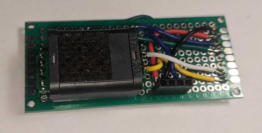
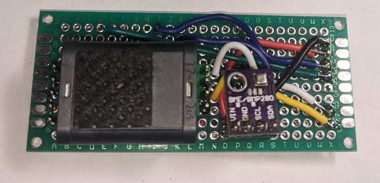
Finally place a BME280 breakout board into the socket. See image below:-